Sheet Metal Fabrication Process: Complete Guide & Steps
Industrial manufacturing, infrastructure, and commercial facilities rely heavily on custom metal components that meet demanding mechanical and structural standards. From large HVAC ventilation systems to complex architectural enclosures and industrial machinery housings, custom fabrication provides the foundational building blocks for modern enterprise systems. Understanding the complete sheet metal fabrication process provides plant engineers, contractors, and project developers with the insights necessary to optimize part geometry, control production expenses, and maintain rigorous material tolerances.
Sheet metal fabrication converts flat stock ranging from thin aluminum alloys to heavy gauge carbon and stainless steel into fully realized components and assemblies through engineered mechanical alteration. Rather than casting or additive modeling, this subtractive and forming discipline relies on specialized machinery, disciplined tooling sequences, and skilled craftsmanship.
What Is the Sheet Metal Fabrication Process?
At its core, the sheet metal fabrication process refers to the comprehensive manufacturing sequence used to cut, shape, join, and finish flat sheets of metal into functional assemblies. Sheet stock typically ranges in thickness from thin foil gauges up to 0.25-inch plate. Once raw metal exceeds a quarter-inch, fabricators classify the material as structural plate, which often requires different handling equipment and thermal cutting techniques.

Modern fabricators balance speed, repeatability, and structural integrity across diverse industry sectors:
| Fabrication Phase | Primary Operations | Common Machinery Employed | Core Deliverables |
| 1. Engineering | CAD layout, flat-pattern nesting, DFM analysis | SolidWorks, AutoCAD, CAM software | Machine G-code, cut lists, bill of materials |
| 2. Separation | Shearing, laser cutting, plasma cutting, punching | CNC fiber lasers, mechanical shears, turret presses | Dimensional blanks, pierced holes, exterior contours |
| 3. Forming | V-bending, roll forming, wiping, curling | CNC press brakes, hydraulic plate rolls | Flanges, curved channels, structural angles |
| 4. Joining | TIG welding, MIG welding, riveting, spot welding | Robotic weld cells, orbital welders, rivet guns | Structural weldments, unified enclosures |
| 5. Finishing | Deburring, abrasive blasting, powder coating | Blast cabinets, curing ovens, plating baths | Corrosion resistance, aesthetic surface treatment |
Phase 1: Design, Detailing, and Material Selection
Every production run begins with computer-aided design (CAD) modeling. Design engineers define the component’s three-dimensional geometry and unfold it into a two-dimensional blank layout. CAM software incorporates material-specific stretch allowances—calculated via the neutral axis K-factor—to ensure that when a flat blank bends, its external dimensions align precisely with engineering drawings.
Selecting the right metal alloy governs the success of subsequent steps:
- Cold-Rolled Steel (CRS): Provides a uniform surface finish and tight dimensional control; ideal for indoor industrial enclosures and ducting.
- Stainless Steel (304 / 316): Offers superior corrosion resistance and high-temperature tolerance, making it indispensable for chemical processing, water filtration, and food facilities.
- Aluminum (5052 / 6061): Combines lightweight characteristics with high strength-to-weight ratios and natural oxide protection against oxidation.
- Galvanized & Carbon Steel: Delivers cost-effective structural strength for outdoor venting, framing, and commercial HVAC networks.
Phase 2: Cutting, Piercing, and Shearing Methods
Once the flat profile is verified, the blank must be separated from standard sheet stock (commonly 4×8, 5×10, or 6×12-foot sheets). Fabricators select cutting methods based on material type, thickness, and edge quality specifications.
High-Precision CNC Laser Cutting
Fiber laser cutting systems direct a focused beam of amplified light, aided by assist gases like nitrogen or oxygen, through the workpiece. Fiber lasers deliver rapid cycle times, minimal heat-affected zones (HAZ), and microscopic kerf widths. This makes them ideal for intricate geometries, fine hole arrays, and close-tolerance industrial panels.
Waterjet and Plasma Cutting
For thicker gauges or reflective metals, alternative cutting methods take precedence:
- High-Definition CNC Plasma: Uses an electrically ionized gas stream to cut conductive metals up to several inches thick. Plasma cutting provides an economical solution for heavy industrial components where extreme edge finish is secondary.
- Abrasive Waterjet: Utilizes ultra-high-pressure water (up to 90,000 psi) mixed with garnet abrasive. Because it generates no heat, waterjet cutting eliminates thermal distortion, structural hardening, and edge discoloration on sensitive alloys.
Mechanical Shearing and Punching
When producing straight-line cuts across large plates, mechanical shears offer rapid throughput with zero consumable gas cost. Concurrently, CNC turret punch presses stamp standard perforations, knockouts, countersinks, and louvers into sheet stock far faster than beam cutters.
Phase 3: Forming, Bending, and Shaping
After blank separation, the flat piece transitions into a 3D component through plastic deformation. The metal must be stressed beyond its yield point without exceeding its ultimate tensile strength, which would lead to surface cracking or micro-fracturing along bend lines.
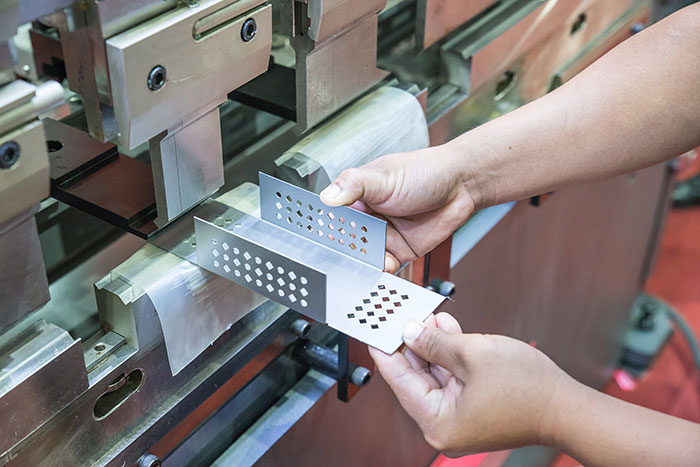
Press brake operators position the blank over an open die bed while a descending punch applies calculated tonnage:
- Air Bending: The workpiece contacts only the punch tip and the upper shoulders of the V-die. This versatile approach allows different angles to be formed simply by adjusting punch depth.
- Bottom Bending (Bottoming): The sheet is forced entirely into contact with the die angle, ensuring higher repeatability and reducing elastic springback.
- Coining: The punch penetrates the material with immense tonnage, permanently altering the grain structure at the bend radius. While coining eliminates springback, it demands substantial machine capacity.
For circular ducts, storage silos, and curved transitions, fabricators run sheets through adjustable three-roll or four-roll plate benders. This process gradually curls flat stock into uniform cylinders and cones.
Phase 4: Welding, Assembly, and Structural Integration
Complex industrial fabrications rarely consist of a single bent sheet; they require rigid joining of separate brackets, flanges, and side walls. Experienced welders evaluate thermal input carefully to prevent buckling and warping across broad sheet panels.
- TIG Welding (GTAW): Employs a non-consumable tungsten electrode and shielding gas to produce exceptionally clean, spatter-free joints. TIG represents the industry standard for stainless steel, sanitary piping, and aesthetic architectural metalwork.
- MIG Welding (GMAW): Delivers a continuous wire feed that expedites structural joins on medium-to-heavy carbon steel assemblies.
- Resistance Spot Welding: Clamps overlapping sheets between copper alloy electrodes, passing electrical current to create localized fusion nuggets without adding filler metal.
- Mechanical Fastening: Employs self-clinching PEM hardware, structural rivets, and engineered bolt circles to connect dismountable or pre-finished surfaces without heat.
For turnkey mechanical systems and heavy industrial plants, fabricators also integrate these assemblies directly with structural piping, platforms, and duct networks. Industrial contractors like Walter N. Yoder & Sons Sheet Metal Fabrication Services maintain specialized in-house facilities equipped with heavy shearing, breaking, and rolling machinery to produce heavy-gauge ductwork, wind systems, and structural assemblies.
Phase 5: Surface Finishing, Quality Assurance, and Standards
The final phase shields the fabricated component against environmental corrosion, eliminates sharp handling edges, and establishes the required visual aesthetic.
Surface Preparation and Coating
- Mechanical Deburring & Graining: Rotary brush machines and belt sanders strip micro-burrs, soften cut edges, and apply linear grain textures across brushed panels.
- Abrasive Media Blasting: Enclosed blast rooms remove mill scale, surface oxides, and weld heat discoloration, creating an anchor profile for paint adhesion.
- Industrial Powder Coating: Positively charged polymer powder is electrostatically sprayed onto grounded parts and baked inside high-temperature curing ovens, creating a hard, resilient finish.
- Chemical Plating & Anodizing: Dipping parts into chemical conversion baths (such as zinc chromate or sulfuric acid anodizing) shields aluminum and steel against aggressive galvanic corrosion.
Dimensional Quality Assurance
Modern quality control departments verify dimensional accuracy through laser scanners, optical comparators, and coordinate measuring machines (CMM). These tools benchmark finished assemblies directly against the original CAD model. Fabricators benchmark processes against technical protocols defined by the NIST Manufacturing Extension Partnership and the Sheet Metal and Air Conditioning Contractors’ National Association (SMACNA) to guarantee structural safety, air-handling tightness, and field fitment.
Selecting an Industrial Fabrication Partner
Navigating the sheet metal fabrication process requires evaluating a vendor’s equipment footprint, workforce certifications, and project management capabilities. Reliable fabricators support customers from early design for manufacturability (DFM) through cutting, certified welding, surface finishing, and field installation. Partnering with an experienced, fully equipped fabrication facility minimizes lead times, eliminates costly field modifications, and ensures that every custom component performs reliably in challenging industrial environments.